Check out the all parts of the Mortal Kombat Arcade Cabinet from Arcade1UP serie:
- Part 1: out of the box
- Part 2: Raspberry PI and custom buttons and joystick
- Part 3: More buttons
- Part 4: Sound and lights
I decided to add a second control deck to this cabinet using the wood panel that already came with the original machine. My initial plan was to add 4 more buttons so each player would have 2 extra buttons for games that requires a lot of buttons.
Prototyping
Before committing to a layout and irreversible woodworking I build a crude but functional prototype out of cardboard.
The prototype was important to realize this was not the layout I wanted. I wanted more buttons. The original control deck has 7 buttons for each of the 2 players. Usually this would be enough but you have to use one of them to the start button and another for coin button. You also need a special button to exit the emulator. That’s 3 out of 7 buttons. Only 4 left for the core gameplay itself. Because this machine should be generic for many types of games I decided to add 3 more buttons for each player so each player has a total of 10 buttons.
The cardboard prototype is an optional step but it was easy and quick to do, it’s fully functional, and provided me some insights for the next steps. I used a piece of cardboard and put the panel J to trace a copy over it using a pencil. Then I cut the cardboard using a craft knife and also cut holes for the buttons. I installed it i the buttons, put the cardboard in the same place of the Panel J, put the wires, and configured the software. I could use the machine like this for some weeks before I moved to the next phase.
Layout
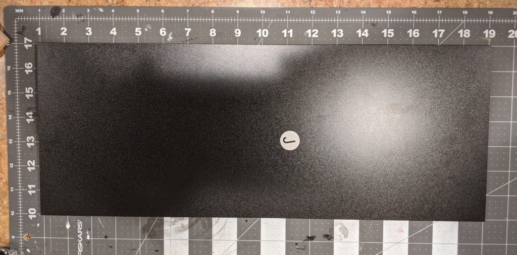
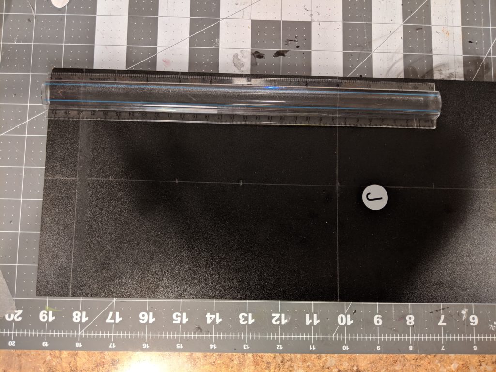
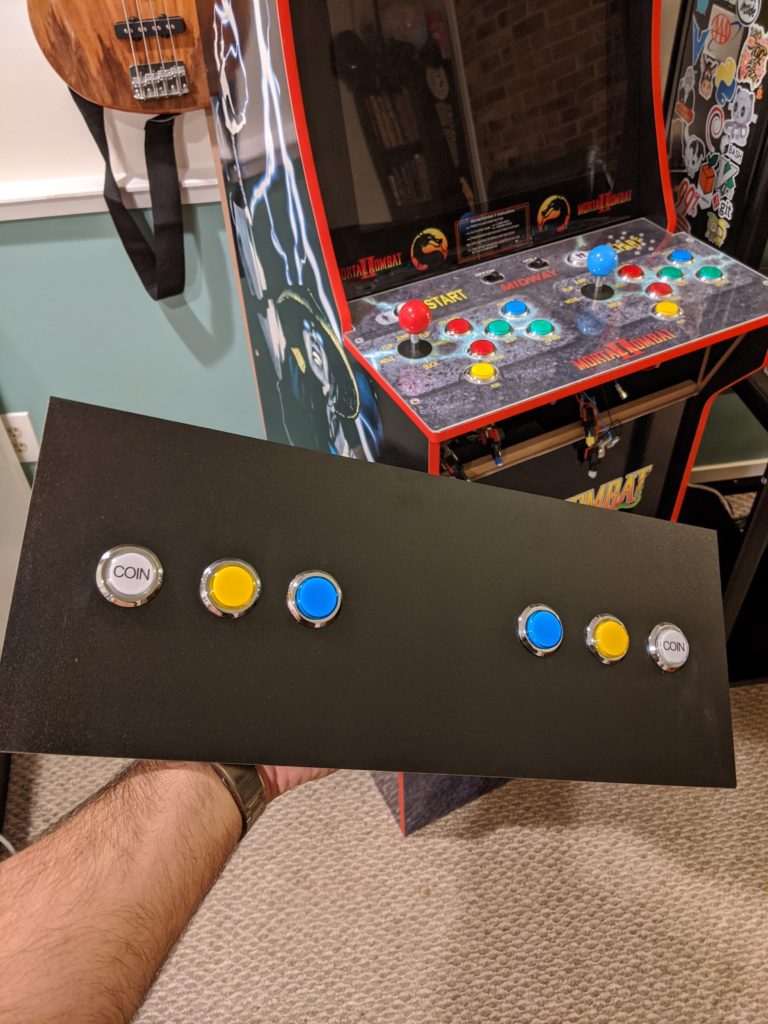
I don’t have a lot of experience with wood so this was my attempt. I had this piece of black coated plywood (45.72 x 17.78 cm ~ 18 x 7 inches) and I wanted to put 6 arcade buttons on it.
First I needed a layout for the buttons. By using the prototype for a while I wanted the buttons in the middle of the panel. Some margin from the sides. Some space in the middle for some future project. The method I used to make the lines using a mechanical paper and a rule is the following:
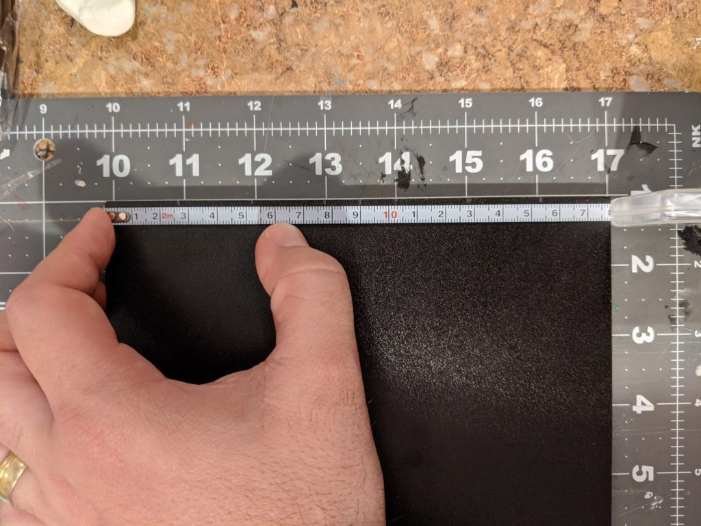
- First, I measure the number I want on one side. Here, I wanted a straight line in the middle of the panel. I get the height of the panel (7 inches ~ 17.78 cm) divide it by 2 (3 ½ inches ~ 8.89 cm) and mark it down using a mechanical pencil.
- Second, I do the same thing in the opposite side of the panel.
- Third, I trace a line between those two points. As I don’t have a rule long enough for this line I used a metal tape measure. Any long straight object will do.
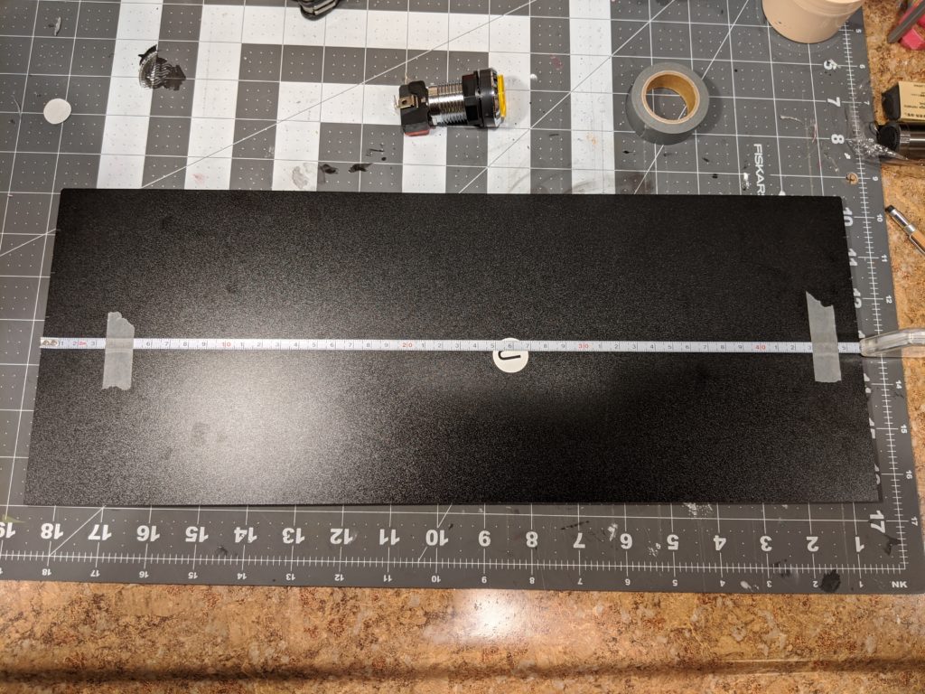
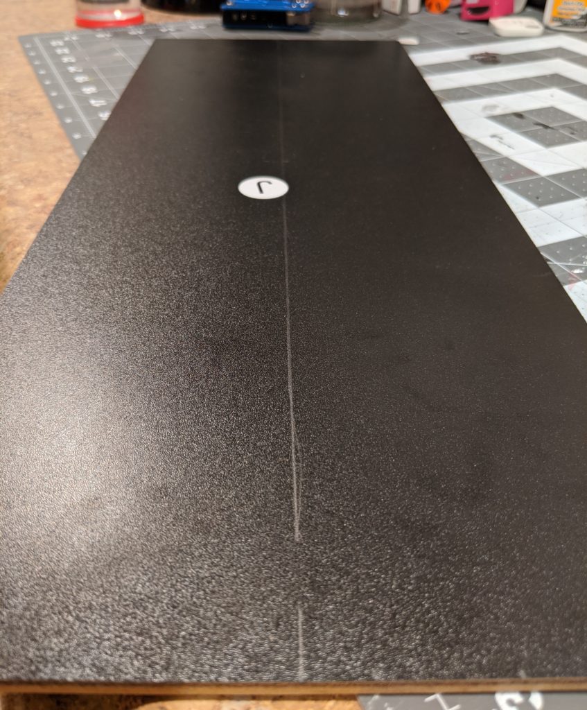
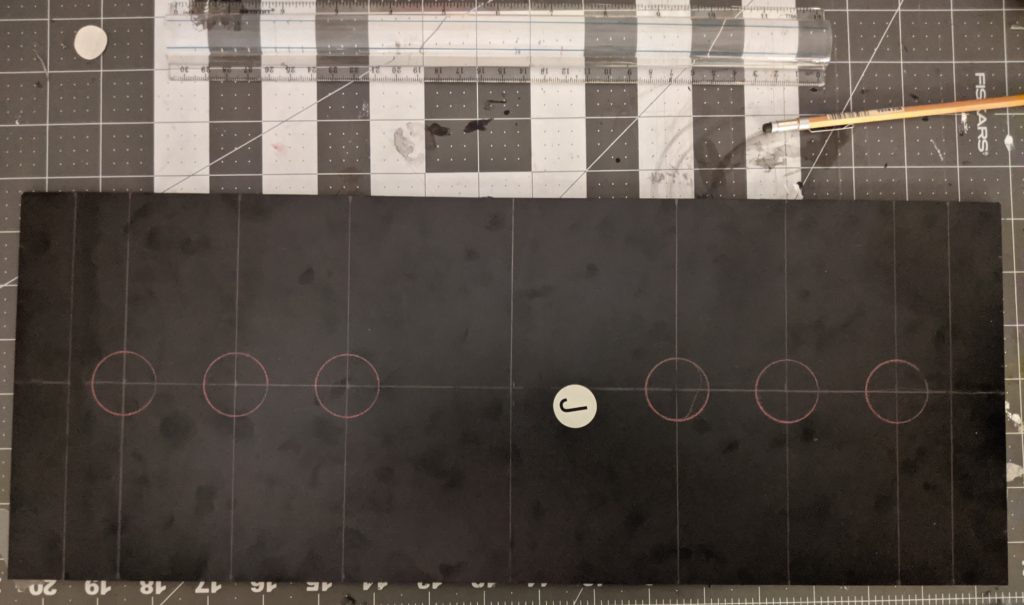
Now repeating this process I got a perpendicular line in the middle of the panel. Then other 2 lines each 1 each away from the border.
Then I did moved another 1 inch to mark where the first button was going to be. This way the first button center is 2 inches away from the border. From this center I moved 2 more inches to find the next center. And then did the same for third center. I repeated the same process for the second player.
I happen to have this circles template that is very handy here. The circle I need is 1 â…› ” (2.8575 cm) and I could use the template to test if the button fits before committing to the whole size. It fits perfectly. This is the same whole size for the other buttons in this Arcade1Up.
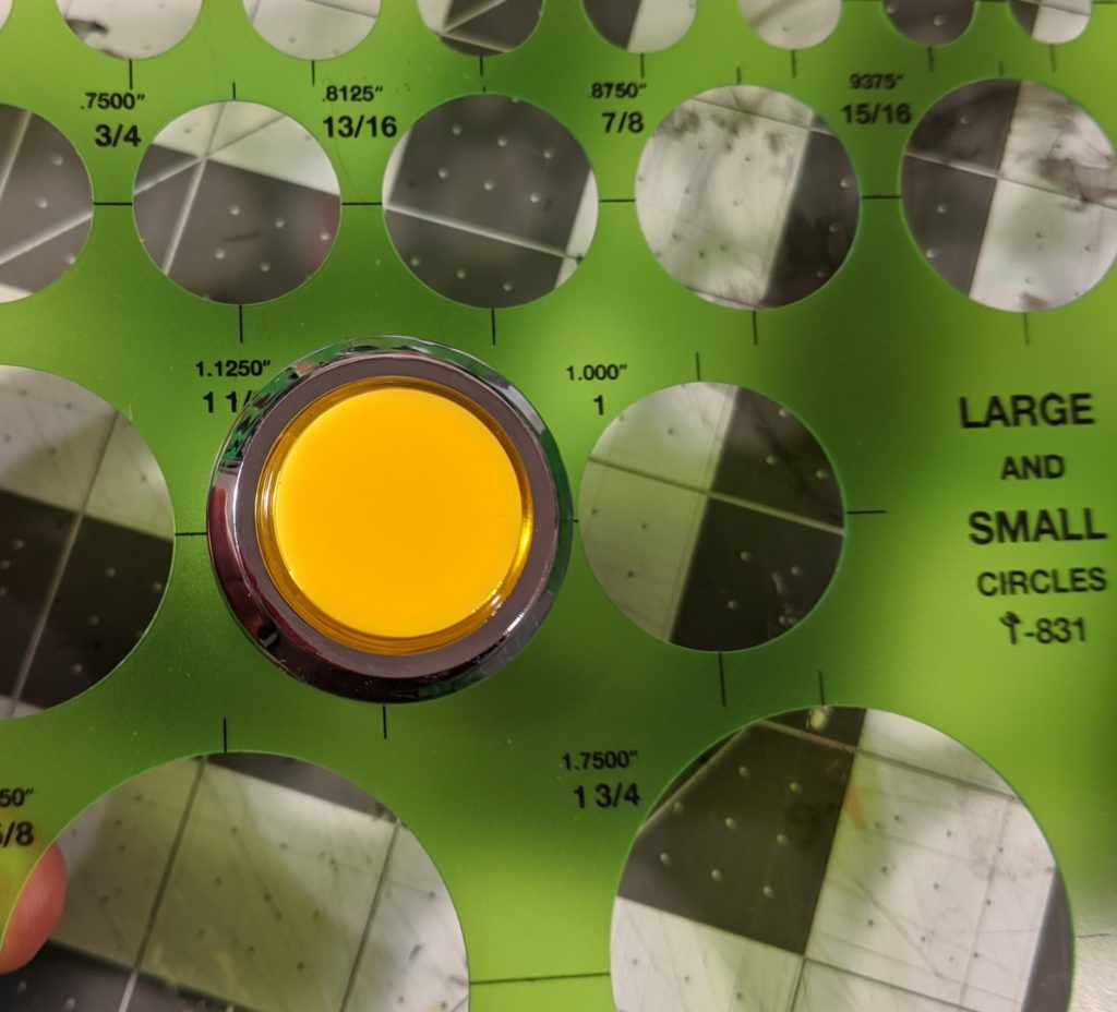
Using red graphite and the circles template I made the circles where the buttons would be. This step is not really necessary but I wanted to be sure this looks okay before doing the holes.
Woodworking
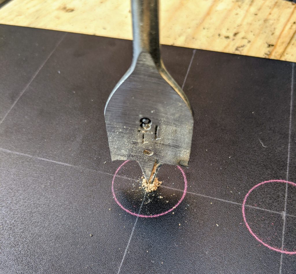
I put a old piece of wood bellow the panel I’m going to drill. This way when I go over the panel I will not hit the table. I’m using a 1 â…› ” spade drill from this drill bit set and a Black & Decker LD120VA drill.
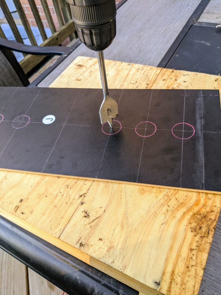
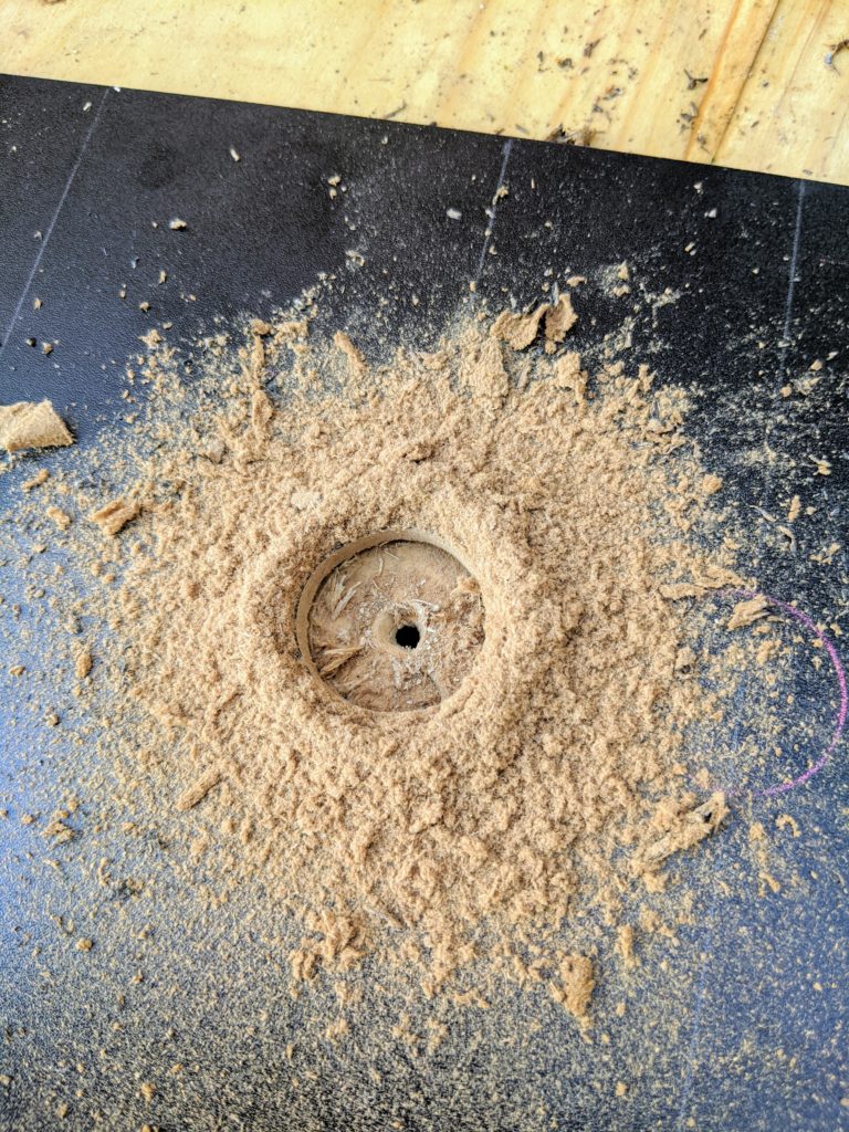
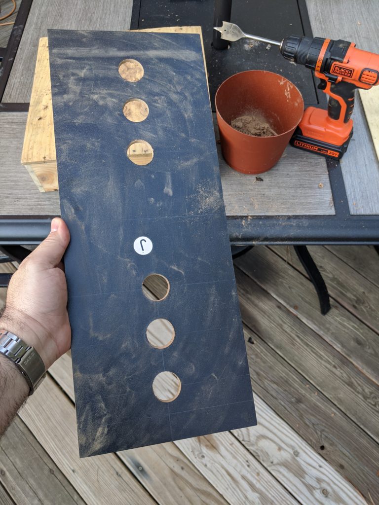
On one side the wholes where clean but in the other side there were these ugly “exit wounds”. As I said, I don’t have a lot of experience with wood. Fortunately this board is the same both sides and I could just clean the side that was supposed to be hidden and use as a front panel.
Buttons
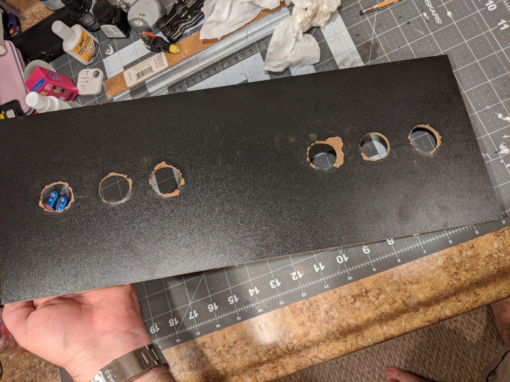
Buttons installation is just like it was on part 2. In total I could use all the buttons that came with the kit.
They are close enough from the control board so the wires can reach the connectors. Here I’m glad I did the cardboard prototype because I knew I didn’t need to extend these wires.
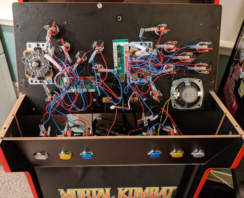
As far as configurations go it is the same as in part 2. These buttons behave just like any of the other buttons. For the Raspberry PI this is a computer with two USB joysticks plugged on it. Each with 10 buttons and the directional which is the same as another 4 buttons.
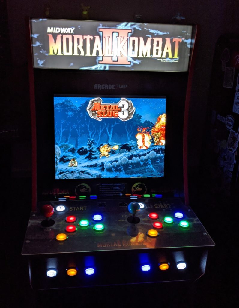
Conclusion
Now this machine has two joysticks and 20 buttons and 2 joysticks. That is enough to play all the games I want. On the next part of this tutorial I will show how to add better sound and even more lights.
“How could I have avoided this?â€
Drill from both sides.
Thanks. I think to align the two holes I could have drilled a little hole in the center of the circle and used that to guide the two holes, right?
The spade bit does that for you already 🙂
Nice cab!
Hole method 1: Use a hole saw and put masking tape down on the laminated surface.
Hole method 2: Drill a pilot hole in the center and then enlarge it from both sides using a step bit.
Note: Paddle bits aren’t really intended for finish work.
Cool. I will try that next time. I will also update the post to give these tips.